RoRD Layout Adaptation Report: Model Adjustments for IC Template Recognition
Jul 22, 2025
An AI Path for Layout Template Recognition
This report continues the direction of the initial RoRD report and focuses more specifically on adapting RoRD to IC layout template recognition: removing modules designed for natural images, forcing the model to learn layout geometry, and handling multi-scale matching in large layouts.
Date: July 22, 2025
Type: Opening report
Core topic: model adaptation, loss-function optimization, and initial experiments for RoRD in IC layout recognition.
Project Goal: Supporting DTCO
The goal is to build an AI layout analysis engine that uses RoRD to automatically decompose IC layouts, connect design and manufacturing feedback, and support PPA optimization for advanced process nodes.
| Direction | Goal |
|---|---|
| DTCO acceleration | Provide a data-inspection tool that helps optimize design-process co-optimization workflows. |
| PPA improvement | Automatically identify standard cells and IP modules for fast area, density, and congestion analysis. |
| Yield protection | Identify risky patterns and avoid potential manufacturing defects at the design stage. |
| IP verification | Automatically verify implementation consistency of IP blocks in final layouts. |
Core Challenges In Layout Recognition
Efficient and accurate template recognition must first address four core challenges.
| Challenge | Description |
|---|---|
| Data scarcity | Supervised learning requires large amounts of fine-grained labeled data, but pixel-level and bounding-box annotations are expensive in layout domains. |
| Geometric variation | IC layouts commonly involve 8 orientations: 0, 90, 180, and 270 degree rotations, plus horizontal or vertical mirroring under these rotations. |
| Dynamic extensibility | IP and standard-cell libraries are large and frequently updated, so models must adapt to new templates without repeated retraining. |
| Structural complexity | IC layouts contain dense, fine-grained geometry and hierarchical structures, placing high demands on representation learning. |
AI Method Comparison
The original report used interactive tabs to compare methods. Here the same content is converted into Markdown tables so it fits the current blog architecture.
| Dimension | U-Net | YOLO | Transformer / ViT | SuperPoint | RoRD |
|---|---|---|---|---|---|
| Core principle | Semantic segmentation | Object detection | Global self-attention | Self-supervised local features | Rotation-robust local features |
| Strength for layout recognition | Pixel-level contours | Fast detection | Strong global context | Lower annotation burden and better new-template adaptation | Strong rotation robustness and zero/few-shot potential |
| Main challenge | Very expensive labels | Dense small targets and class explosion | Huge data demand and high compute cost | Sparse textures and repeated structures | Large-scale matching efficiency |
| Data strategy | Many pixel-level labels | Many bounding-box labels | Massive pretraining data | Synthetic data and homographic adaptation | Synthetic rotation data and rotation homography augmentation |
| New-template adaptation | Poor; retraining needed | Poor; retraining needed | Medium; depends on pretraining and fine-tuning | Good | Excellent |
| Rotation robustness | Low | Low to medium | Medium; data-dependent | Medium to high | Very high |
Method Flow Summary
| Method | Core flow |
|---|---|
| U-Net | Input image -> encoder -> decoder -> segmentation mask |
| YOLO | Input image -> backbone -> feature fusion -> bounding boxes and classes |
| Transformer / ViT | Input image -> patch embedding -> Transformer encoder -> feature representation |
| SuperPoint | Input image -> shared CNN -> interest-point detection head -> descriptor head |
| RoRD | Image pair -> Vanilla D2-Net and RoRD feature extraction -> MNN matching -> correspondence integration and RANSAC |
RoRD Deep Dive: Why This Method?
RoRD, or Rotation-Robust Descriptors and Orthographic Views for Local Feature Matching, combines augmentation-based invariant descriptor learning with orthographic view projection to handle local feature matching under extreme viewpoint changes.
Component 1: Orthographic View Generation
RoRD uses orthographic views to increase visual overlap and assist matching, but orthographic views alone are not enough for extreme viewpoint changes. Rotation-robust features are still required.
The main methods include:
- Surface-normal based generation: depth information is used to build a 3D point cloud, estimate the dominant plane normal, and generate an orthographic view.
- Inverse perspective mapping (IPM): a fixed homography maps camera images to bird’s-eye-view images.
Component 2: Rotation-Robust Descriptor Learning
This is the core component for rotation invariance. The goal is to learn local descriptors that remain stable and discriminative even under in-plane rotation.
The rotation homography is:
Key techniques:
- Data augmentation: random in-plane rotation homographies are applied during training, with the rotation angle uniformly sampled from 0 to 360 degrees.
- Network architecture: the model is based on D2-Net’s joint detection-and-description framework and uses VGG-16 as the backbone.
- Training objective: descriptors from original image patches and geometrically transformed corresponding patches are encouraged to stay close in feature space.
Component 3: Correspondence Integration And Filtering
RoRD introduces correspondence integration and uses RANSAC for geometric verification to improve final matching accuracy.
- Dual-head D2-Net: one head is trained like original D2-Net, while the other is trained with rotation-augmented data.
- Independent matching and merging: both heads detect keypoints, compute descriptors, and establish initial matches using MNN.
- RANSAC verification: outliers are filtered from the merged match set, leaving geometrically consistent matches.
By combining orthographic view generation, rotation-robust feature learning, and correspondence integration, RoRD significantly improves local feature matching under extreme viewpoint changes, especially rotation.
Adapting RoRD For IC Layouts
The original RoRD targets real-world 3D scene images. To apply it to IC layout recognition, it must be adapted around binary data, sparsity, Manhattan geometry, and repeated structures.
1. Remove Orthographic View Generation
In the original RoRD pipeline, orthographic view generation corrects perspective distortion caused by camera viewpoints. IC layout data, such as GDSII and OASIS, is precise 2D geometric vector data and is already a distortion-free top-down representation.
Therefore, for this task, orthographic view generation is unnecessary and can be removed. Rasterized layout images can be used directly as model input, simplifying the pipeline and avoiding interpolation artifacts.
2. Adapt To Sparse And Binary Features
IC layout images usually contain only foreground geometry and background. Large regions are blank, and many repeated structures exist, such as SRAM arrays. This challenges feature extractors pretrained on natural images.
Adaptation strategies:
- Focus on corners: make the detector respond to polygon vertices and edges rather than blank regions or simple straight lines.
- Use layout-specific augmentation: replace color and lighting augmentation with geometric transformations such as rotation, scaling, and mirroring.
- Learn geometric descriptors: make the descriptor learn local geometric configurations instead of natural-image texture.
3. Optimize The Loss Function: Learning Geometry, Not Texture
To force the model to learn IC layout geometry rather than natural-image texture, this report customizes the original loss function. The key idea is to add constraints for binary images, sparsity, Manhattan geometry, and repeated structures.
The total loss is:
Detection Loss: Adapting To Binary Images
The detection loss is tuned to handle black-and-white layout images and improve boundary localization:
Here:
- BCE is the dominant term and is suitable for binary pixel detection.
- Smooth L1 is an auxiliary term that improves geometric edge localization and helps reduce false positives in repeated structures.
Geometry-Aware Descriptor Loss
The descriptor loss combines an enhanced Triplet Loss with three regularization terms designed for IC layout geometry:
Triplet Loss With L1 Distance
The Euclidean distance (L2) in the original Triplet Loss is replaced by Manhattan distance (L1), which better fits grid-like Manhattan geometry:
Geometry Regularization Terms
| Loss term | Role |
|---|---|
| Enforces descriptor consistency under 90-degree rotations, directly targeting rotational symmetry and repeated layout structures. | |
| Applies L1 regularization to encourage sparse descriptors and reduce invalid features in blank regions. | |
| Computes distance on descriptor signs, strengthening geometric-boundary learning and reducing sensitivity to gray-level variation. | |
| Geometry-aware hard negative mining | Prioritizes negative samples that become geometrically similar to the anchor after Manhattan transformations but remain structurally different. |
4. Introduce Multi-Scale Matching
In real applications, the template and the full layout may differ drastically in size. A template may be only a few hundred pixels wide, while a full layout may reach hundreds of thousands of pixels. Direct matching is impractical.
The following strategies can be used:
- Sliding windows: extract features in fixed-size windows over the large layout and map them back to global coordinates.
- Image pyramids: build a multi-scale template pyramid to search under unknown scale.
- Scale jittering: introduce random scale changes during training to improve descriptor robustness.
With sliding windows, image pyramids, and scale jittering, RoRD can search for templates of unknown size in arbitrarily large layouts, making it better suited to real IC layout recognition tasks.
Initial Experiments
The following are examples of RoRD-based IC layout matching.
| keypoints | raw-match | RANSAC-match |
|---|---|---|
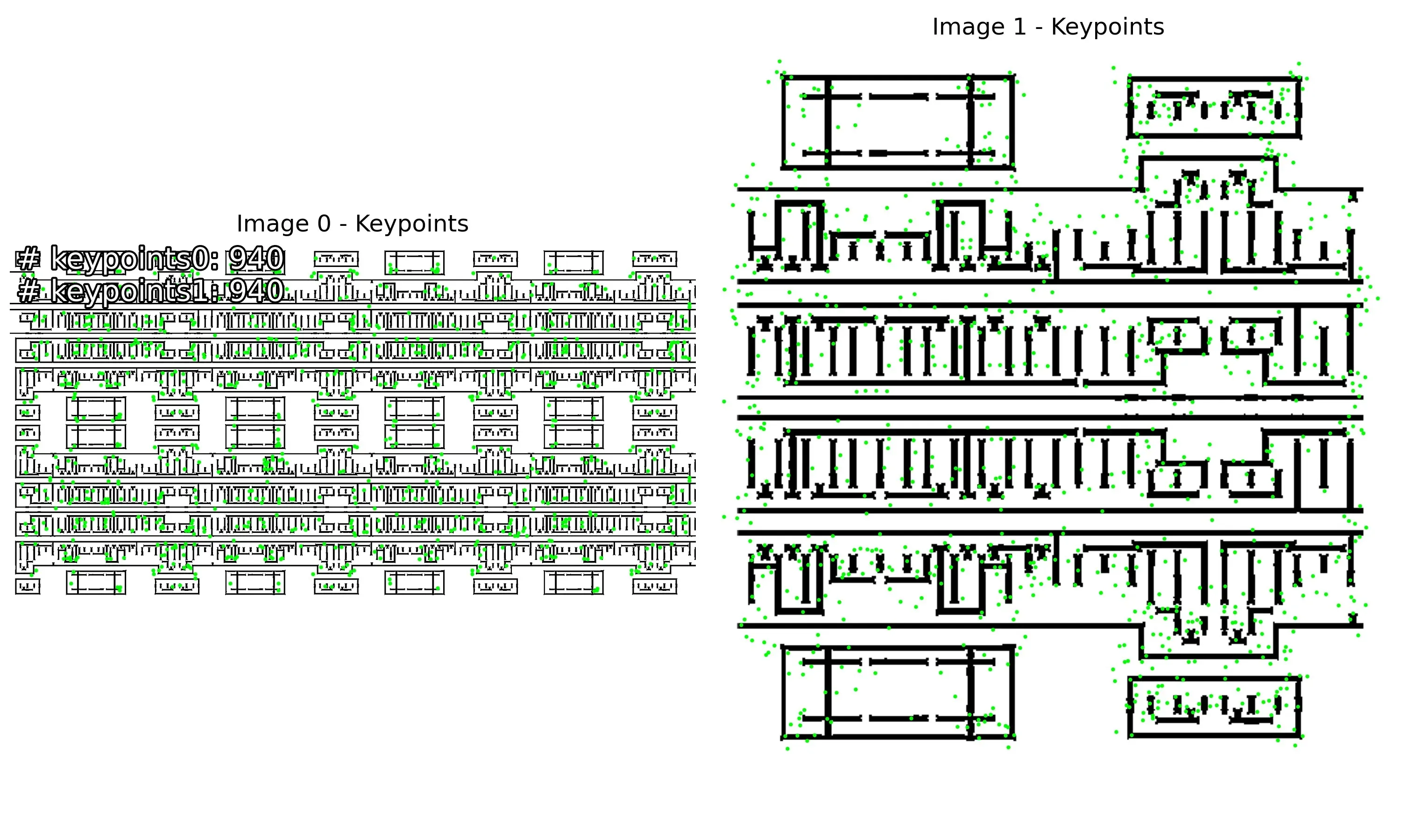 | 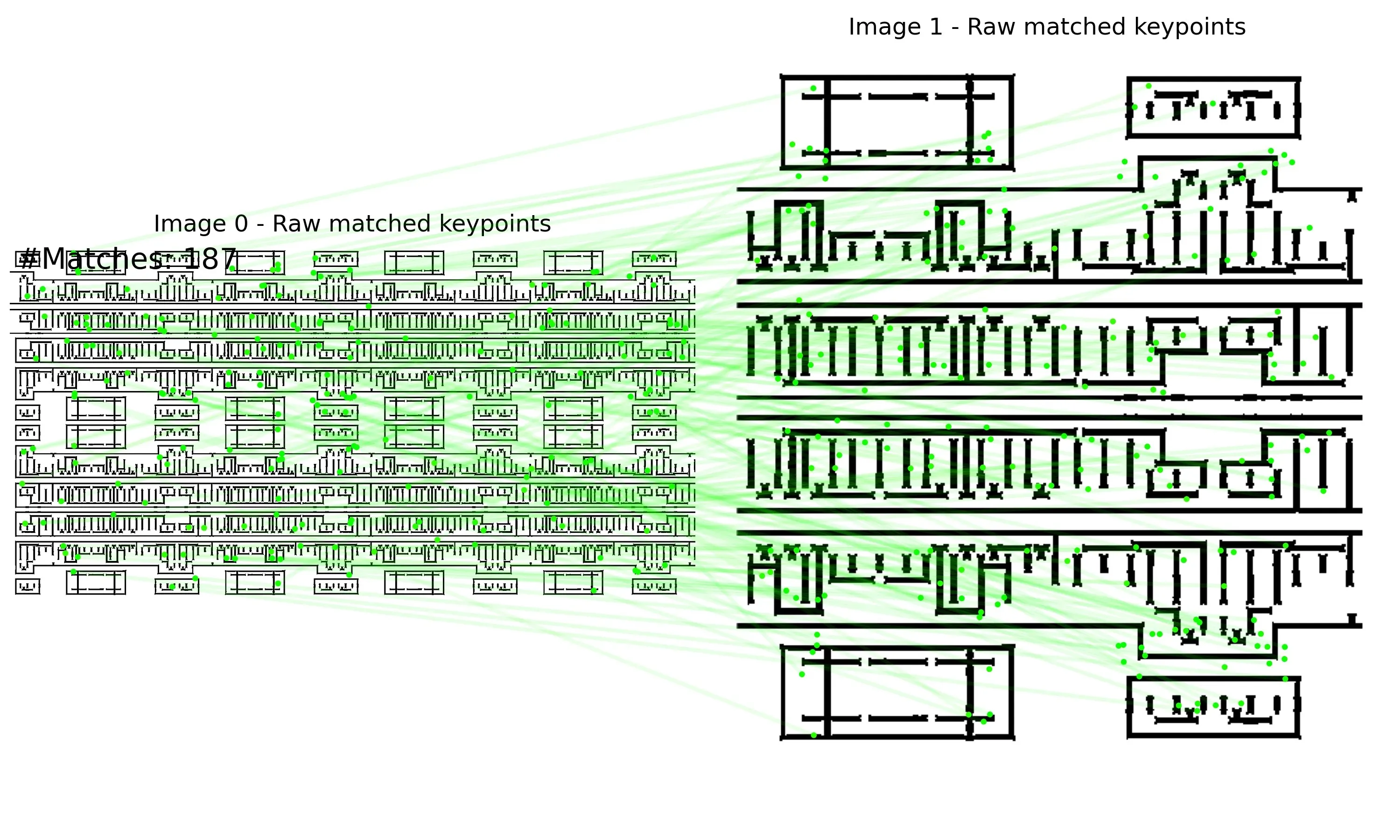 | 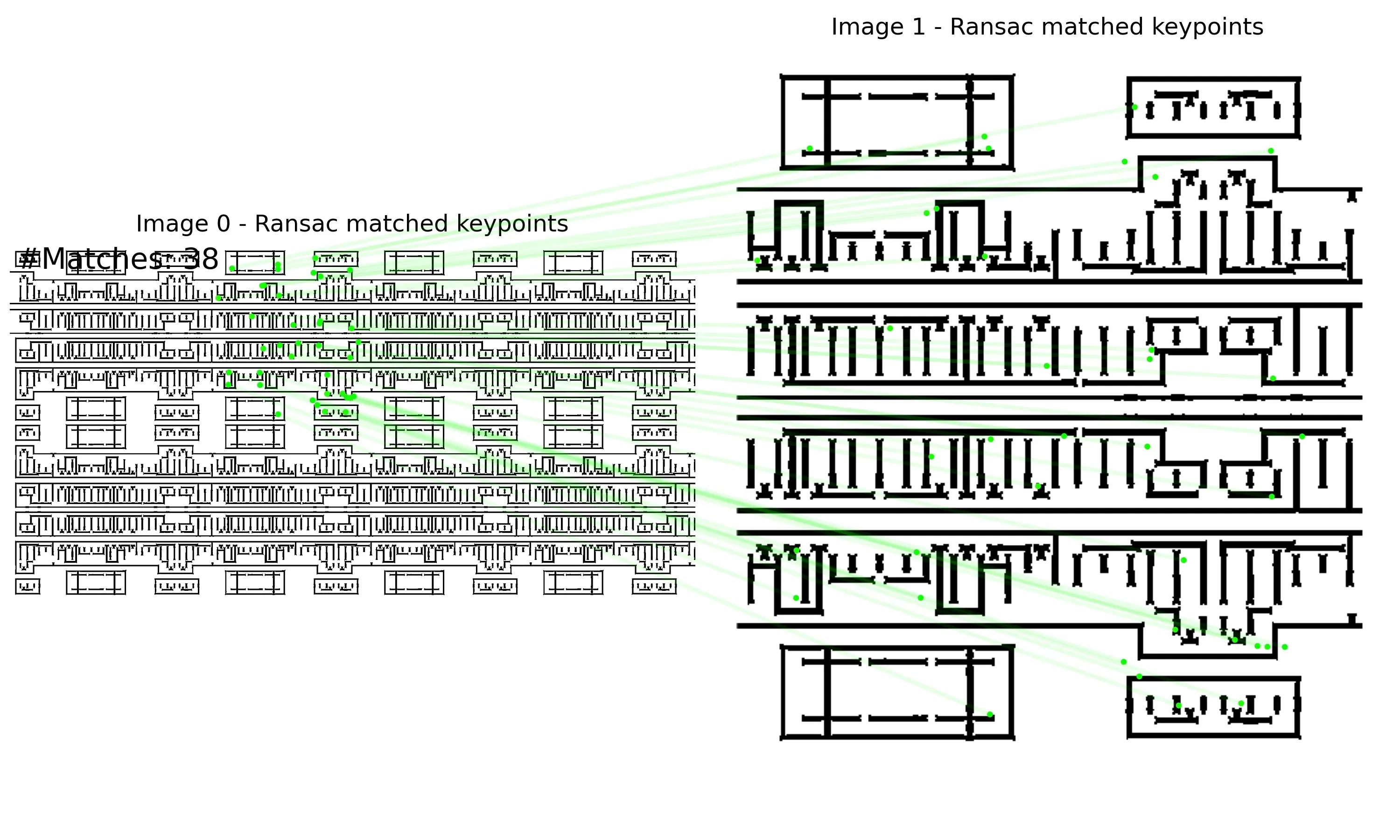 |
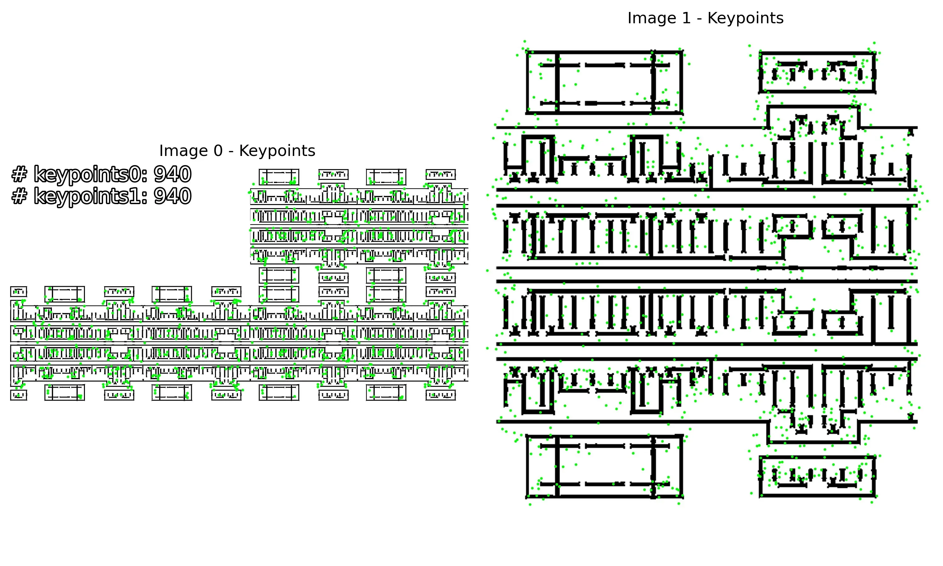 | 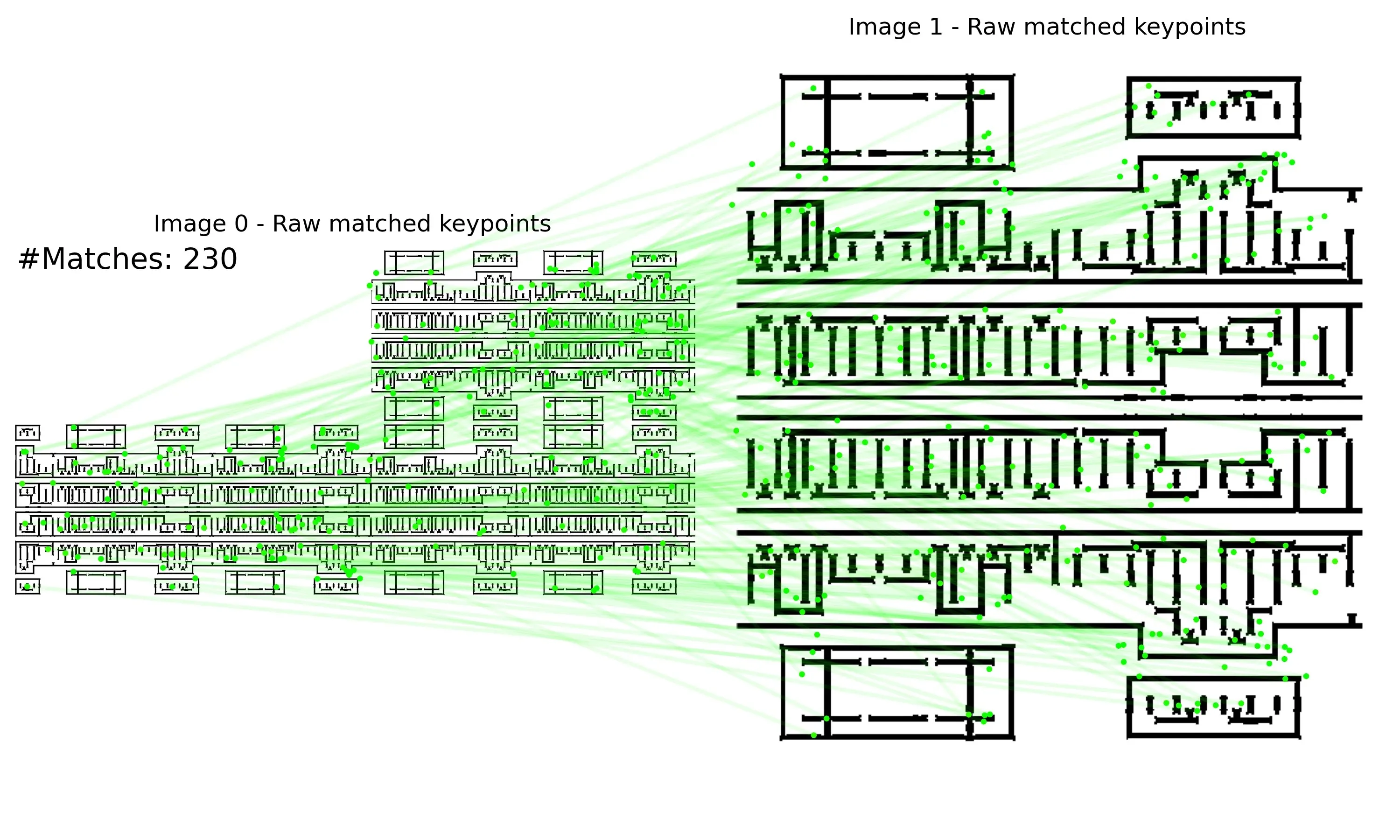 | 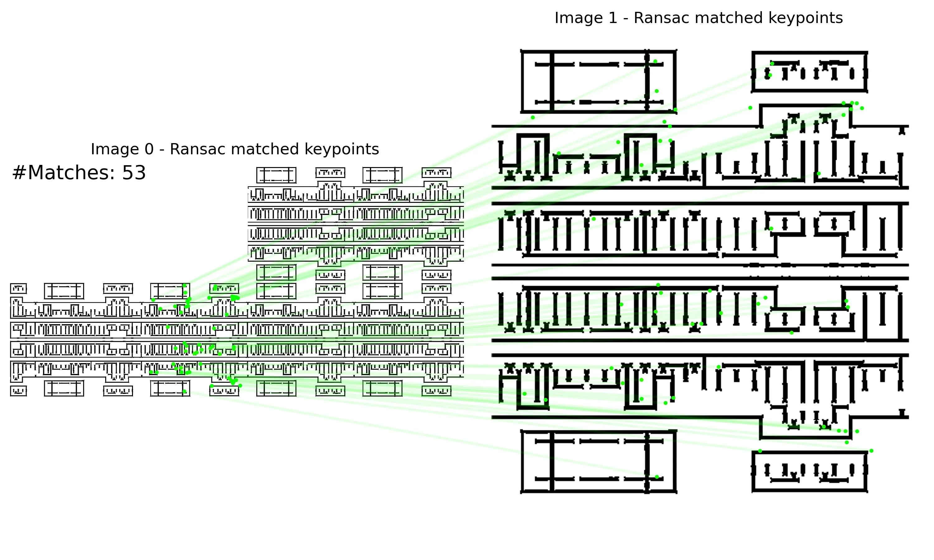 |
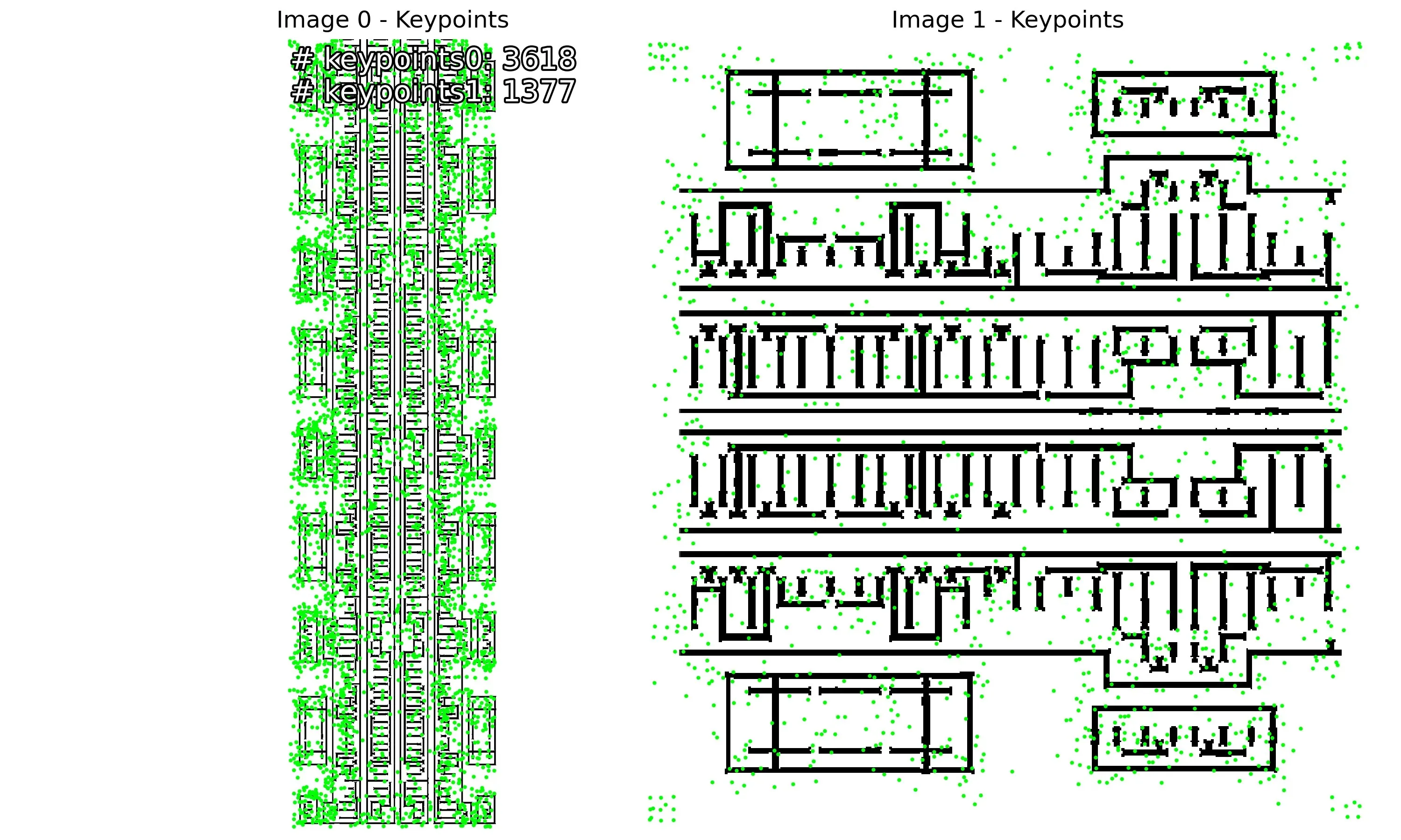 | 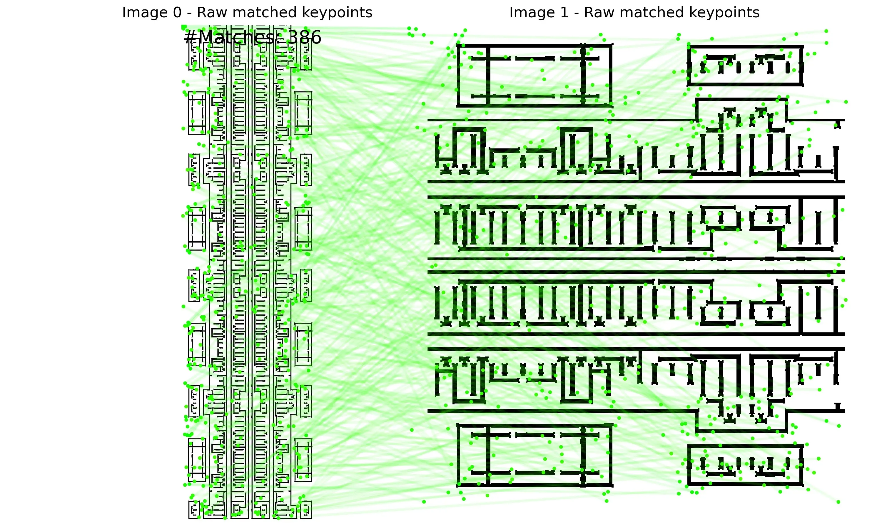 | 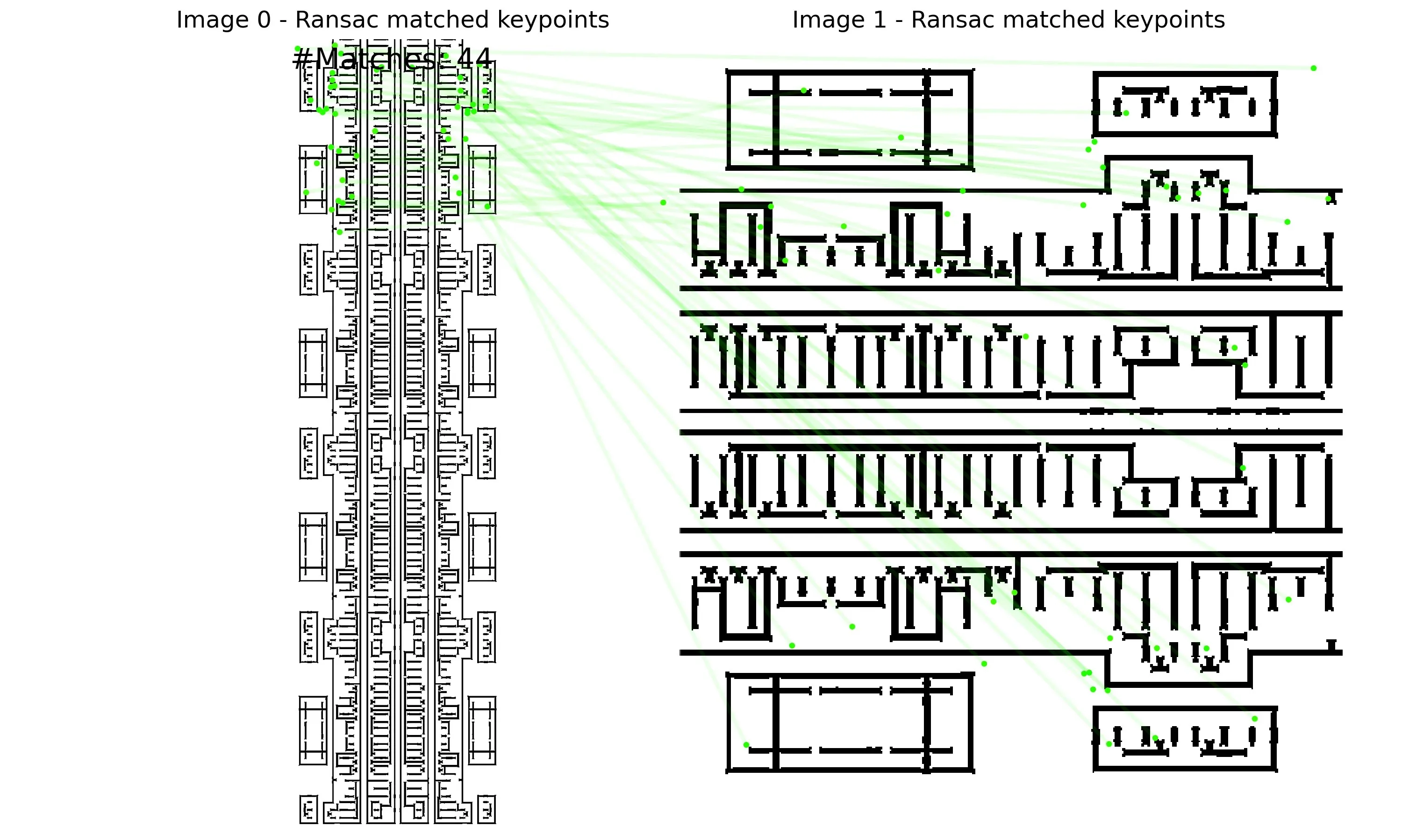 |
Applications And Future Work
Future Priorities
- Model optimization: continue improving the RoRD architecture and training strategy for sparse binary layouts.
- Better discriminability: study new loss functions to improve descriptor separation in highly repeated structures.
- Large-scale matching acceleration: implement and optimize approximate nearest neighbor (ANN) search for massive template libraries.
- End-to-end system integration: integrate RoRD into a complete layout analysis pipeline for circuit analysis and defect diagnosis.
Project Timeline
| Milestone | Goal |
|---|---|
| Before July 2025 | Complete IC-layout-specific RoRD implementation and initial debugging. |
| Before February 2026 | Complete private dataset annotation, model training, and validation. |
| Before June 2026 | Complete performance optimization and code refactoring, write the paper, and attempt submission. |
Summary
Compared with the initial report, this version goes one step further. It does not only explain why RoRD is suitable for layout template recognition, but also proposes a concrete adaptation path for IC layouts. The core idea is to keep RoRD’s rotation-robust descriptor and geometric verification framework, remove redundant modules from natural-image tasks, and use geometry-aware loss design, multi-scale matching, and layout-specific augmentation so the model truly learns layout structure.
Loading comments...